
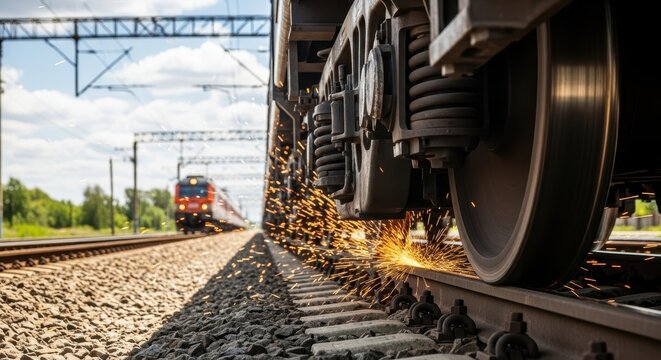
This product delivers a high-performance and reliable solution for restoring rail surfaces affected by defects such as corrugation, spalling, flanging, fish-scale patterns, and side wear. With high-precision milling and grinding technology, it produces a smooth and accurate rail profile while eliminating defects completely in a single pass—significantly reducing maintenance time and operational disruption. Its combination of high performance and low lifecycle cost makes it a smarter and more cost-effective investment compared to conventional equipment.
Designed for maximum flexibility, the system can be applied before the commissioning of new railway lines, on long-idle tracks, and on rails requiring corrective maintenance. Its stage operation—high-efficiency precision grinding, high-quality results across all applications.
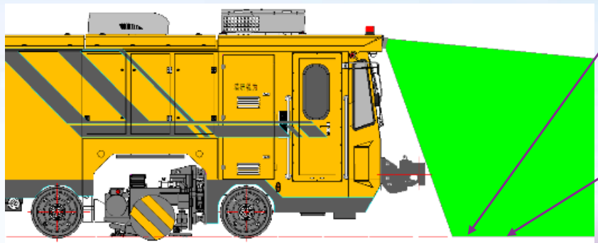
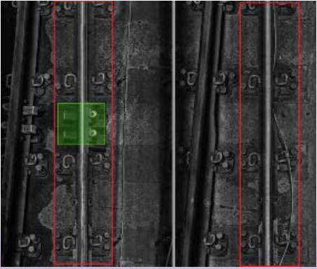
To further enhance safety and operational reliability, the system is equipped with an advanced rail obstacle recognition system powered by image recognition technology. Front-mounted sensors continuously scan the track, detecting obstacles such as trackside lubricators, axle counters, and other equipment, and providing real-time alerts to operators—minimizing risks and preventing potential incidents.
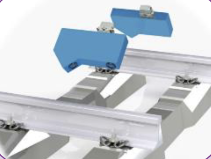
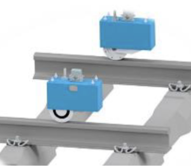
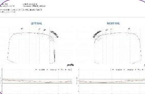
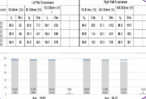
In addition, the integrated on-board rail profile and corrugation measurement system delivers real-time monitoring with high accuracy of up to ±0.1 mm. This ensures compliance with required standards, maintains optimal rail performance, and provides accurate data to support faster and more confident technical decision-making. The system fully complies with international standards EN13231-3 and TB2658.22.
Proven in real-world operations, this solution has been successfully deployed by leading operators such as MTR and Zhengzhou Metro, with extensive maintenance work completed across major metro networks in Beijing, Nanjing, Suzhou, and Guangzhou. Furthermore, we are capable of providing customized designs and rail milling machines tailored to meet the requirements of various national standards.
Rail Obstacle Recognition System
Rail Profile & Corrugation Measurement System
Environmental Operating Specifications
Parameter | Value |
Climate Conditions | Suitable for typical urban climate conditions in China |
Maximum Altitude | 2,000 m above sea level (a.s.l.) |
Relative Humidity | ≤95% (monthly average, at minimum ambient temperature of 25°C) |
Parking Requirements | Vehicle must be parked and maintained indoors in a workshop; indoor workshop temperature shall not fall below –10°C |
Operating Conditions | Capable of all-weather operation — including rain, snow, wind, and sandstorms — and fully functional in tunnels and during nighttime operations |
Track Conditions Specifications
Parameter | Value |
Gauge Clearance (Vehicle Limit) | Complies with CJJ 96-2018 limits for vehicle types A1, A2, B1, and B2 |
Track Gauge | 1,435 mm |
Rail Types Supported | 50 kg/m, 60 kg/m, and 75 kg/m rails |
Maximum Superelevation | 175 mm |
Minimum Horizontal Curve Radius | 50 m |
Minimum Vertical Curve Radius | 2,000 m |
Maximum Gradient | 50 ‰ (i.e., 5% or 50 mm rise per meter of horizontal distance) |
Rail Sleepers (Ties) | Concrete sleepers and wooden sleepers |
Ballast Type | Crushed stone ballast and slab track (ballastless track) |
Turnout (Switch) Numbers | • Mainline: No. 9 and No. 12 turnouts |
Track Conditions Specifications
Parameter | Value |
Gauge Clearance (Vehicle Limit) | Complies with CJJ 96–2018 limits for vehicle types A1, A2, B1, and B2 |
Track Gauge | 1,435 mm |
Rail Types Supported | 50 kg/m, 60 kg/m, and 75 kg/m rails |
Maximum Superelevation | 175 mm |
Minimum Horizontal Curve Radius | 50 m |
Minimum Vertical Curve Radius | 2,000 m |
Maximum Gradient | 50 ‰ (i.e., 50 mm rise per meter of horizontal distance) |
Rail Sleepers (Ties) | Concrete sleepers and wooden sleepers |
Ballast Type | Crushed stone ballast and slab track (ballastless track) |
Turnout (Switch) Numbers | • Mainline: No. 9 and No. 12 turnouts |
General Technical Description
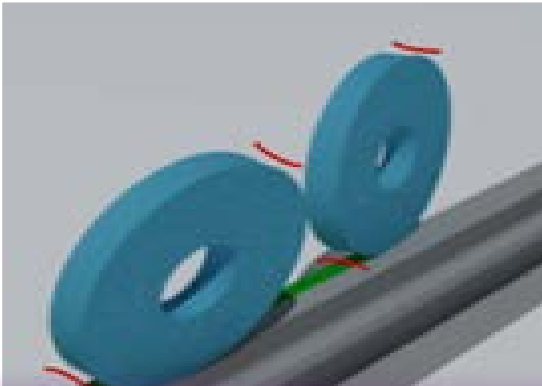
The CMC-12 Rail Milling Train is a new-generation rail grinding vehicle with a compact design, utilizing a face grinding method equipped with 12 grinding heads, capable of performing grinding operations on both mainline tracks and switches. This vehicle is designed to repair various types of rail defects, including:
Ø Rail profile deformation,
Ø Rail corrugation,
Ø Rail material loss (spalling), and
Ø Surface cracking such as rail squats / fish-scale cracking.
This equipment is fully compliant with EN and ISO standards and is compatible with UIC, Chinese, and US rail profiles, ensuring seamless integration across diverse railway systems. It offers a reliable, future-ready solution for efficient and standardized rail maintenance.
In addition, the vehicle is equipped with an automatic rail detection system, as well as an advanced dust collection system using cartridge filter technology, which captures and recycles iron particles generated during the grinding process—ensuring clean, efficient, and environmentally friendly operations.
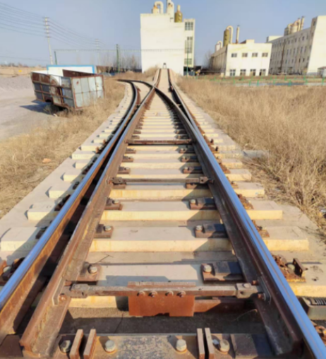
Grinding Wheels Grinding Effecft
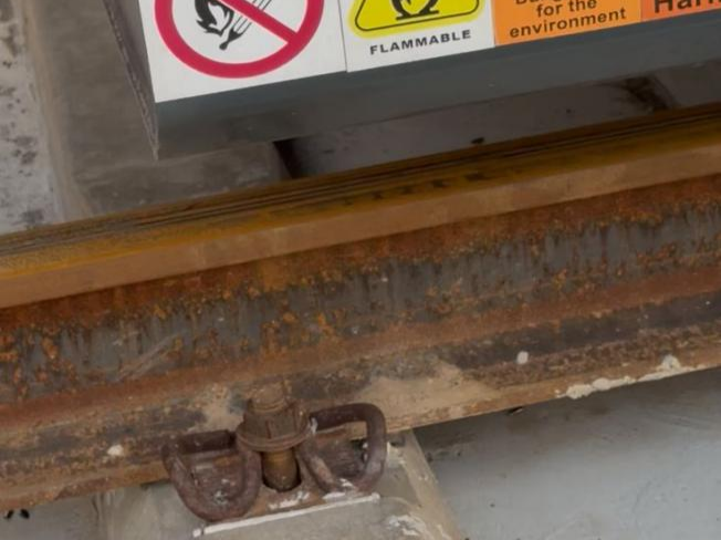
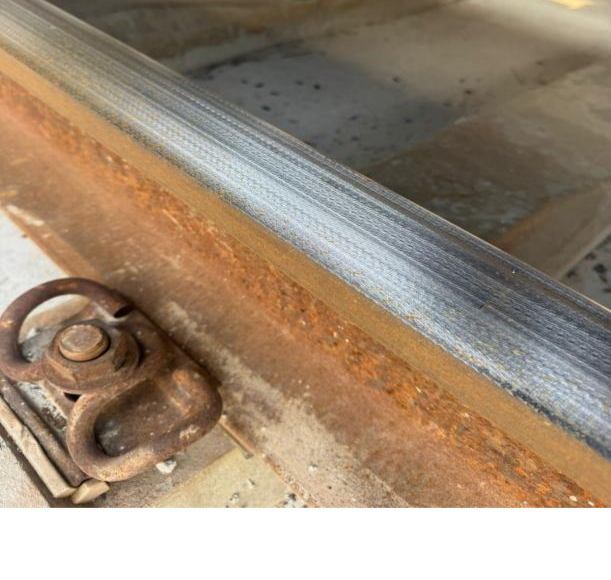
Before After
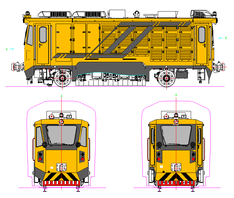
Definition of Vehicle Ends and Sides
Ø The end equipped with the larger operator cab is defined as End I.
Ø The end equipped with the smaller operator cab is defined as End II.
Ø The left and right sides of the vehicle are determined based on the operator’s position in the cab at End I: when facing forward, the operator’s left-hand side corresponds to the left side of the vehicle, and the right-hand side corresponds to the right side of the vehicle.
Ø Wheelsets (axles) are numbered sequentially from End I to End II as Axle 1 and Axle 2. Wheel identification follows the vehicle side convention: for example, the left wheel of Axle 1 is designated as 1L, the right wheel of Axle 2 as 2R, and so on.
Grinding Head Numbering
Ø Numbering starts from the rear of the cab at End I.
Ø Left side: 1L, 2L, …, 6L
Ø Right side: 1R, 2R, …, 6R
Ø Units 1L, 1R, 6L, and 6R are dedicated to rail profile grinding (profile grinding units).
Ø The remaining 8 units (2L–5L and 2R–5R) are used for rail corrugation grinding (corrugation grinding units).
Coordinate System
Ø X-axis: Longitudinal direction (positive direction toward End I)
Ø Y-axis: Lateral direction (positive direction toward the left side of the vehicle)
Ø Z-axis: Vertical direction (positive direction upward)
Ø Coordinate origin: The intersection point of the X, Y, and Z axes, defined as the intersection of the vehicle centerline, the midpoint between the inner faces of the wheels, and the top surface of the rail.
Train Parameters
Parameter | Value |
Overall Dimensions (L × W × H) | 9,400 mm × 2,575 mm × 3,445 mm |
Tare Weight (Ready-to-Operate Mass) | ≤27 tonnes |
Axle Load | ≤13.5 tonnes (further reduction possible) |
Axle Arrangement | A₀–A₀ |
Wheel Diameter | Ø740 mm (new), Ø670 mm (fully worn) |
Tread Profile | LM-type tread |
Track Gauge (Wheel Internal Distance) | (1,353 ± 2) mm |
Cabin Noise Level | ≤75 dB(A) |
External Noise Level | ≤82 dB(A) — measured at 7.5 m from track centerline, 1.2 m above rail top, alongside vehicle |
Electromagnetic Compatibility (EMC) Standards | Complies with EN 50121-3-1, EN 50121-3-1 & EN 50121-3-2 |
Design Service Life | ≥30 years |
Major Overhaul Interval | ≥10 years |
Engine Make & Model | Dongfeng Cummins / QSL8.9-G33 |
Rated Engine Power & Speed | 270 kW / 1,500 rpm |
Generator Make & Model | Leroy Somer / LSA 46.3L11 |
Generator Output (Power / Frequency / Voltage) | 230 kW / 50 Hz / AC 400 V |
Fuel Tank Capacity | 500 L |
Brake System Make & Model | Knorr / KE1dv |
Braking Deceleration (on straight, level track) / Stopping Distance | • Maximum service braking: ≥1.0 m/s² |
Minimum Negotiable Curve Radius | 50 m |
Coupler Type | Type 2 coupler |
Coupler Height | (880 ± 10) mm |
Transmission System | AC–DC–AC electric transmission |
Air Reservoir Capacity | 2 × 225 L |
Continuous Operating Duration | ≥8 hours |
Operational Performance
Parameter | Value |
Maximum Speed | 60 km/h |
Construction/Work Train Speed | 66 km/h |
Minimum Negotiable Curve Radius | 50 m |
Maximum Admissible Gradient | 50 ‰ (i.e., 50 mm vertical rise per meter of horizontal distance) |
Dynamic Performance Compliance | Meets GB/T 17426 — “Dynamic Performance Test Standards for Railway Maintenance Vehicles” |
Grinding Performance Specifications
Parameter | Value |
Number of Grinding Heads | 12 units total: |
Grinding Angle Range | –70° to +15° |
Grinding Speed Range | 3–16 km/h (adjustable in real time) |
Speed Control Accuracy | ±0.1 km/h |
Minimum Curve Radius During Grinding | 50 m |
Maximum Gradient During Grinding | 50 ‰ |
Grinding Depth per Pass | 0.1 mm (measured at nominal grinding speed of 7 km/h) |
Surface Roughness (Ra) After Grinding | ≤10 µm |
Grinding Taper (Transition Gradient) | 1 ‰ (programmable and adjustable per section) |
Grinding Motor Power | 15 kW per head |
Grinding Motor Speed | 3,000–4,000 rpm |
Grinding Wheel Diameter | 260 mm (standard coarse-duty), 150 mm (precision/contouring variant) |
Airflow Rate (Dust Extraction System) | ≥2,400 m³/h (at filter inlet, fully loaded condition) |

 English
 Русский